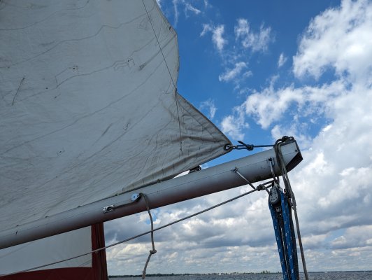
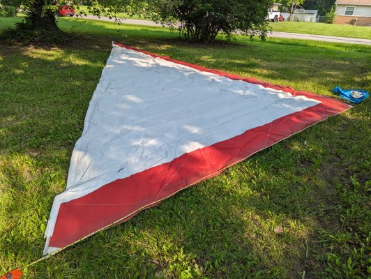
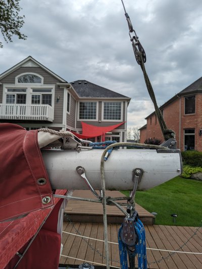
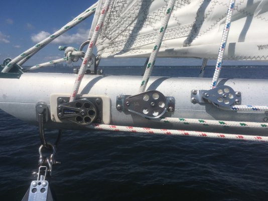
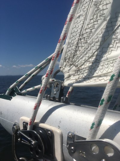
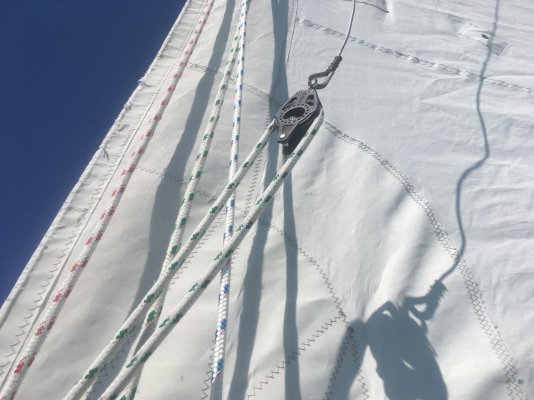
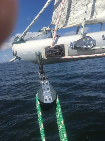
Ahh, that all makes sense, yes, I can attach that block to the topping lift, the shackle is missing though, might have to take a trip to the local West Marine (sadly....). I have a pulley on the side of the boom, just under the first reef point, I figured that was for the first reef, I'll look for the other line then. As for the car for the tack, it's not there, and the bracket I have the topping lift on, it's fastened in place, not in the track, and it's offset to one side ( I think). Wondering if the car is at the front of the boom, if so I'll have to remove the foot of the sail to slide it aft. All my experience with rigging is on the 13' dingy I had, no topping lift, no reefing, so this is all new to me. Learning fast.
I won't be able to go back to the boat for a couple of weeks to fix all this, bummer.
Dave.