• Welcome to this website/forum for people interested in the Morgan 38 Sailboat. Many of our members are 'owners' of Morgan 38s, but you don't need to be an owner to Register/Join.

Alternator Overcharging

Tony Aragon

New Member
Dear members, this is my first post, but I have been a morgan owner and followed this forum for several years. I need some insight from the collective knowledge of this group. I just changed my battery bank to 4 x 6V trojans (flooded) for the house and a 12V 120amp starter. After I finished the installation, I went out and 3 minutes later in the middle of the kemah outlet my Viking battery monitoring system alarm accused over voltage of 15.9V on my battery bank. Since I was in the middle of the channel alone and could not turn off the motor, I decided to disconnect my alternator with the motor running to spare the batteries from the overcharge. This cooked my alternator. My initial thoughts were that my alternators internal voltage regulator was the problem. (I still believe this alternator has an internal voltage regulator correct?)

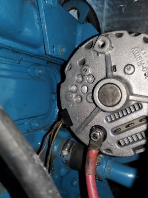
took it to an alternator specialist and he confirmed it was cooked and did a complete rebuild and tested the alternator. I still use the original delco (60 to 80amp) that came with my perkins 4108.

Went back to my boat and after reading several forums, thought the problem was my hook up of the Blue Sea System SI-ACR Automatic Charging Relay that was connected to the same distribution block as the alternators charging port. Changed the outlet of the ACR directly to the battery post as advised in a post and tested again. With the motor on and just taking the RPM to 3000, the voltage did not go over 14V. Thought problem was solved.

Left yesterday to Florida and again the same problem happened as soon as I left the marina. After putting in gear and accelerating the over voltage came back taking the voltage up to 16V. This time I had time to turn off the motor and disconnect the alternator and continue, since I would be in a marina to charge my batteries with the AC power charger.

Can not understand what I did wrong. Below a diagram of my set up. Some help and knowledge would really be appreciated before spending money on a specialized electrician.

Thanks for any input.
 

Attachments

  • Nogara bank Final May 2021.pdf
    270.7 KB · Views: 39
I am having a hard time following your drawing. For me, the pretty drawings with pictures are much harder to follow than an old school schematic. But I can provide some general advice.

Check the sense wire on the back of the alternator. For internal regulators, this wire is normally just connection on the back of the alternator, that goes from one terminal to the other. Perhaps from the "S" terminal to the "B+" terminal. If this wire is not connected properly, the alternator will run at the wrong voltage. Some people run that wire to the battery itself, but I wouldn't bother unless I had an external regulator. If it is not connected at all, then for sure your alternator will run at a very high voltage.

Regarding the ACR, that is what I can't follow on your diagram. The ARC only requires 3 wires, and is very simple to connect. First is the ground, and that looks fine. Then there would be one wire to each battery. I see the wire to your house bank, but the wire that should go to your start battery I can't tell where it goes. It looks like to the starter? It could either go directly to the battery, or to the other side of the isolation switch if you want. I would go to the battery myself. Both of the battery wires from the ARC should be fused.

The 4th wire to the ignition switch is optional. You can leave it disconnected, and only connect it if your chartplotter resets while cranking the engine. With a house bank as large as yours that probably won't happen.
 
Warren,
Thank you very much for your response. Let me try to clarify my schematic a little bit. my alternator has e three wire pin connector (photo below) that all go into the original wire harness. One is for the tach and the other two I believe go to the time control and the battery voltage gauge. I am not sure since I did not follow them to their final destination. Will do that when arrive in a marina that allows me to have good access to the alternator and wiring. The ACR is connected on the house battery bank directly to the positive batty post, and on the starter bank to the positive distribution post of that bank. I have it fused on the starter side and will fuse on the house bank side. I will also disconnect the red wire that I attached from the ACR to the ignition switch. I have no ground wire on the alternator since it is bolted to the engine that is part of the main ground system.

Should I remove the three wires from the connector on the alternator, connect the specific one to the tach and connect the other to together? is that what you are saying? Also I am running my engine all day without the alternator connected to the batteries. Is this OK or will it burn my alternator again?

Thanks again for your patience and willingness to deal with someone that does not have that great of an electrical knowledge.
 

Attachments

  • Original Alternator.jpg
    Original Alternator.jpg
    2.2 MB · Views: 7
Unfortunately, I am not an alternator expert, and there are many different styles that are connected differently. Almost every alternator I have seen uses different colors or markings to indicate what wires do what. You would need to contact that manufacturer of your alternator for a diagram. I expect that one would go to an indicator light or your key switch power. That would be the field wire that powers the alternator. One should just connect back to the main + terminal on the alternator, that is the sense wire that I think is connected wrong. And the other the tach.
 
Last edited:
The details are beyond me. But I would urge you to get a new alternator and a separate voltage regulator (e.g. Balmar Max Charge) and stop using an alternator that is internally regulated. This is especially important since you are now trying to recharge 400 amp hours of house bank. Your internally regulated alternator will never charge that size of house bank anywhere close to full and you will never have anywhere close to your bank's capacity available for use and their longevity will be compromised.
 
I strongly agree with Terry. I had included that recommendation also, but accidently deleted it while editing my response. The stock alternator is acceptable if it will not be frequently used for charging, but instead charging is just a side effect when running the engine anyway.
 
Tony,
Electrical problems are hard to diagnose remotely. But based on your description I would propose hat you have a grounding issue. If I remember correctly, the three wires going to the connector on the back of the alternator are +12v, ground and the alternator field signal. The field signal goes to the tach, the other two go to the internal regulator that controls alternator output. This is where I would start to investigate. Another issue is that the alternator is used as a ground for the charging current. I would suggest adding a #2 cable between the alternator case and the connection on the starter where the starting battery is attached. lastly make sure that the ground connections between the house bank and the starting battery is tight.
I hope this helps. I am at Watergate marina in Kemah, so let me know if you need further help.

Regards,

Jose
 
Back
Top